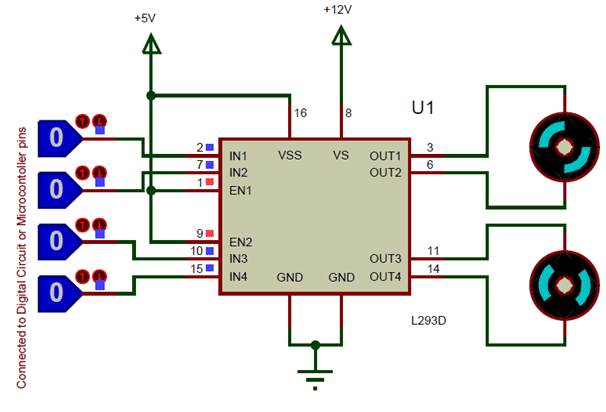
L293d Motor Driver Circuit Diagram Pdf

L293D) solenoids, DC and bipolar stepping motors, as well as. • Peak Output Current 2 A Per. Each output is a complete totem-pole drive circuit. Pin Configuration and Functions. Enable driver channels 1 and 2 (active high input).
Common DC gear head motors need current above 250mA. There are many integrated circuits like ATmega16,. But, IC 74 series cannot supply this amount of current. When the motor is directly connected to the o/p of the above ICs then, they might damaged. To overcome this problem, a motor control circuit is required, which can act as a bridge between the above motors and ICs (). There are various ways of making H-bridge motor control circuit such as using transistor, relays and using L293D/L298. H Bridge Motor Control Circuit Using L293d IC H-Bridge Circuit A H bridge is an electronic circuit that allows a voltage to be applied across a load in any direction.
Torrent losing my religion mp3 download. Oct 19, 2015 Free download R.E.M. – Losing My Religion Mp3. We have about 23 mp3 files ready to play and download. To start this download Lagu you need to click on [Download] Button. Remember that by downloading this song you accept our terms and conditions. 15 Tesco Vee's Hate Police - Losing My Religion.mp3 2,896 KB Ryan Star - Losing My Religion.mp3 2,479 KB Benzedrine Monks Of Santo Domonica - losing my religion.mp3 2,393 KB.
H-bridge circuits are frequently used in robotics and many other applications to allow DC motors to run forward & backward. These motor control circuits are mostly used in different converters like DC-DC, DC-AC, AC-AC converters and many other types of. In specific, a bipolar stepper motor is always driven by a motor controller having two H-bridges H-Bridge Circuit A H-bridge is fabricated with like S1, S2, S3 and S4. When the S1 and S4 switches are closed, then a +ve voltage will be applied across the motor. By opening the switches S1 and S4 and closing the switches S2 and S3, this voltage is inverted, allowing invert operation of the motor. Generally, the H-bridge motor driver circuit is used to reverse the direction of the motor and also to break the motor. When the motor comes to a sudden stop, as the terminals of the motor are shorted.
Or let the motor run free to a stop, when the motor is detached from the circuit. The table below gives the different operations with the four switches corresponding to the above circuit. Operation of the H-Bridge L293D Motor Driver IC L293D IC is a typical Motor Driver IC which allows the to drive on any direction. This IC consists of 16-pins which are used to control a set of two DC motors instantaneously in any direction. It means, by using a L293D IC we can control two DC motors.
 You never worry again to keep your device driver always up-to-date, lets DriverFinder do the job for you. DriverFinder automatically install for your windows PC. DriverFinder is the recommended Driver Update Utility Its no surprise, DriverFinder is recommended by software and computer experts. With its perfect scan technology, huge database, and great support, it's easy to see why. System compatibility Compatible and fully support for Windows 2000, Windows XP, Windows Server 2003, Windows server 2008, Windows Vista, Windows 7, Windows 8.1/8 and Windows 10 for 32 bit or 64 Bit.
As well, this IC can drive small and quiet big motors. Pin Diagram of a L293D Motor Driver IC Controller L293D IC Pin Configuration • Pin-1 (Enable 1-2): When the enable pin is high, then the left part of the IC will work otherwise it won’t work. This pin is also called as a master control pin. • Pin-2 (Input-1): When the input pin is high, then the flow of current will be through output 1 • Pin-3 (Output-1): This output-1 pin must be connected to one of the terminals of the motor • Pin4 &5: These pins are ground pins • Pin-6 (Output-2): This pin must be connected to one of the terminals of the motor. • Pin-7 (Input-2): When this pin is HIGH then the flow of current will be though output 2 • Pin-8 (Vcc2): This is the voltage pin which is used to supply the voltage to the motor. • Pin-16 (Vss): This pin is the power source to the integrated circuit. • Pin-15 (Input-4): When this pin is high, then the flow of current will be through output-4.
• Pin-14 (Output-4): This pin must be connected to one of the terminals of the motor • Pin-12 & 13: These pins are ground pins • Pin-11 (Output-3): This pin must be connected to one of the terminals of the motor. • Pin-10 (Input-3): When this pin is high, then the flow of current will through output-3 • Pin-9 (Enable3-4): When this pin is high, then the right part of the IC will work & when it is low the right part of the IC won’t work.